Ethernet Case Cover
On this page
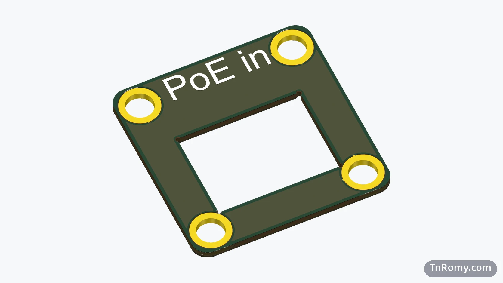
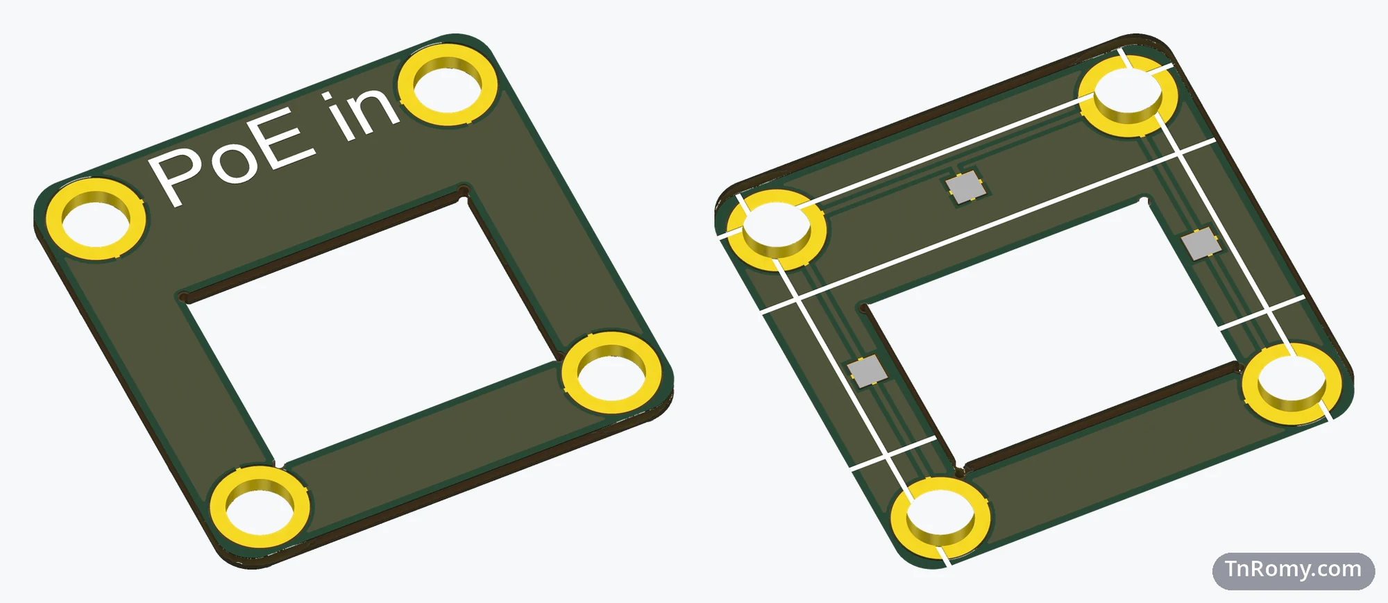
The Ethernet Case Cover is the front end cap of the PoE32 Lite enclosure: a bare PCB of 24.9 × 24.9 mm with a square opening for the RJ45. It has no components and no traces. Its whole job is to close the aluminium profile and put the network port exactly where it belongs.
It is the simplest board in the PoE32 family, and it exists because of a small problem that is easy to underestimate: cutting a clean, accurate rectangular hole in a piece of aluminium.
At a glance
| Board | Ethernet Case Cover, the front end cap of the PoE32 Lite enclosure |
|---|---|
| Revision | v3, ordered in December 2025 |
| Size | 24.9 × 24.9 mm, 1.0 mm thick, 2 mm corner radius, RJ45 opening of 15.5 × 11.35 mm |
| PCB | A bare board with no components and no traces |
| Enclosure | Closes the Ethernet end of the PoE32 Lite aluminium profile |
| Connects to | Nothing electrically; the RJ45 of PoE32 Lite sits in its opening |
| Status | Prototype, together with PoE32 Lite v3 |
| Files | 3D model (STEP) attached below |
Why it exists
The aluminium enclosure comes with aluminium end caps. They are fine as long as nothing has to pass through them, but PoE32 Lite has an RJ45 at one end, and the cap needs an opening that fits the connector closely and sits exactly in the middle. Cutting that by hand in aluminium, accurately and repeatably, is hard.
A PCB manufacturer, on the other hand, cuts board outlines and internal openings to a fraction of a millimetre as a matter of routine. So I replaced the cap with a PCB of the same size and the same bolt pattern, and let the board house do the precise part. No traces, no components: the board is only there for its shape.
The journey
v2: the first cover (May 2025)
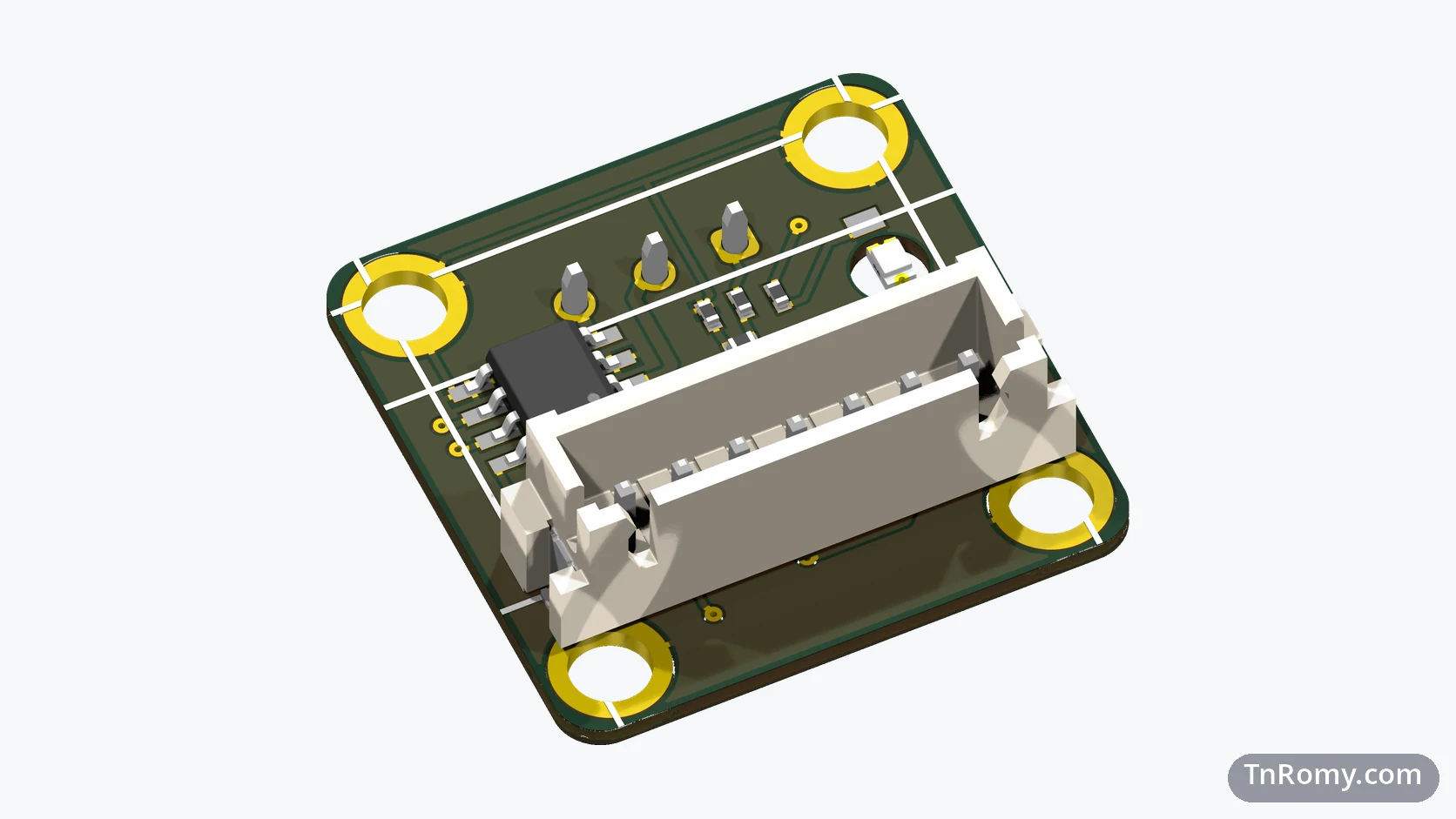
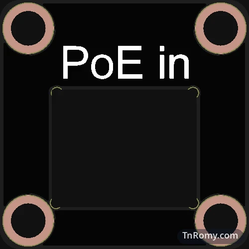
The cover was one of the first things I designed for v2, together with the rear cover, before the main board got its shape. Its opening matched the low-profile RJ45 that PoE32 Lite v2 used, at 14.3 × 11.55 mm, with "PoE in" printed above it.
v3: an opening for a new connector (December 2025)
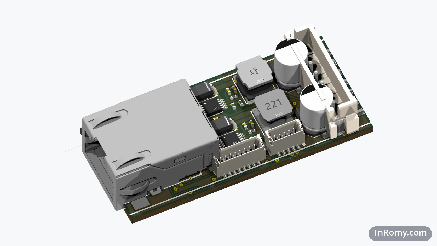
PoE32 Lite v3 switched to an RJ45 with built-in magnetics, which has a different body. The opening followed it and became 15.5 × 11.35 mm. Everything else stayed: the outline, the bolt holes, and the label.
Design decisions
The same outline as every cover. Both end caps of the enclosure share one outline and one bolt pattern, the same as the aluminium caps they replace, so both ends of the profile close the same way.
An opening sized to the connector. The opening follows the body of the RJ45 that sits in it, which is why it changed size when PoE32 Lite changed connectors.
Relief drills in every inside corner. A milling tool cannot cut a perfectly sharp inside corner and leaves a small burr there. A tiny drill hole in each corner of the opening removes that material before the router gets there.
Mechanics
The cover is 24.9 × 24.9 mm with 2 mm corners and 1.0 mm thick. The four bolt holes are 3.42 mm, centred 2.825 mm from the edges, the same as on the rear cover. The RJ45 opening of 15.5 × 11.35 mm has a 0.5 mm relief drill in each of its four inside corners.
What it taught me
Let the factory do the precise part. A board house cuts outlines and openings accurately as a matter of routine. Designing the cover as a PCB turned a fiddly workshop job into a line in a fabrication order.
The outside comes first. Designing the covers before the main board fixed the space the main board had to fit into, and every later revision of PoE32 Lite has been drawn to fit them.
Related
The board whose RJ45 sits in this cover's opening.
Terms
- End cap
- The plate that closes one end of an extruded enclosure profile.
- Board outline
- The shape a PCB manufacturer cuts the board to, including any internal openings.
- Relief drill
- A small hole in the inside corner of a cut-out, so the milling tool does not leave a burr there.
Technologies covered
- Altium Designer
- PCB Design
- Ethernet
Attachments
-
Download
Ethernet-Case-Cover-v3.step (zip)
3D model of the Ethernet Case Cover v3, STEP format
8.0 KB