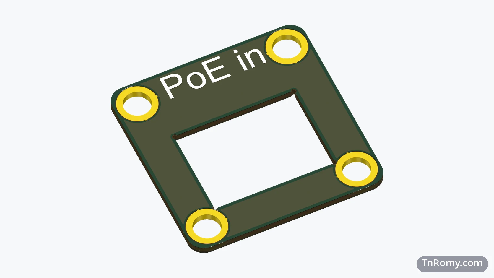
SDFA Module
On this page
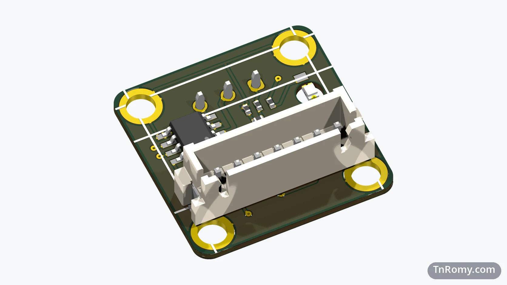
The SDFA Module is the rear cover of the PoE32 Lite enclosure and, at the same time, the circuit that turns PoE32 Lite into a fire alarm node. It is a square PCB of 24.9 × 24.9 mm that closes the back of the aluminium profile, plugs into PoE32 Lite's module header from the inside, and offers a three-wire terminal for the field cable on the outside.
SDFA stands for Software Defined Fire Alarm, the name I gave to the idea behind it. This page follows the module from the first board, where it was not a module at all, to the current revision, which works and is stable.
At a glance
| Board | SDFA Module, the fire alarm module of the PoE32 family |
|---|---|
| Revision | v3, ordered in December 2025 |
| Size | 24.9 × 24.9 mm, 1.0 mm thick, 2 mm corner radius |
| Power | 24 V and 3.3 V from PoE32 Lite, through the module header |
| Interfaces | A 7-pin 2.54 mm header to PoE32 Lite; a 3-pin terminal block for the detector line; one status LED |
| PCB | 2 layers, black solder mask |
| Enclosure | Serves as the rear end cap of the PoE32 Lite enclosure |
| Connects to | The J3 module header of PoE32 Lite, with an identical pinout |
| Status | Working and stable; it goes into real installations together with PoE32 Lite v4 |
| Files | 3D model (STEP) attached below; component values are not published |
Why it exists
The idea is a fire alarm built on an IP network. Every point of the system, a detector or a siren, becomes a network node powered over Ethernet, and the alarm logic lives in software rather than in fixed wiring. PoE32 Lite gives each point its network connection and its power; the SDFA Module is the part that actually talks to the detector.
Keeping that part on its own board is what lets PoE32 Lite stay a general base. The same base with a different rear module becomes a different device, and the fire alarm is simply the first module I built.
The journey
v1: built into the main board (April 2025)
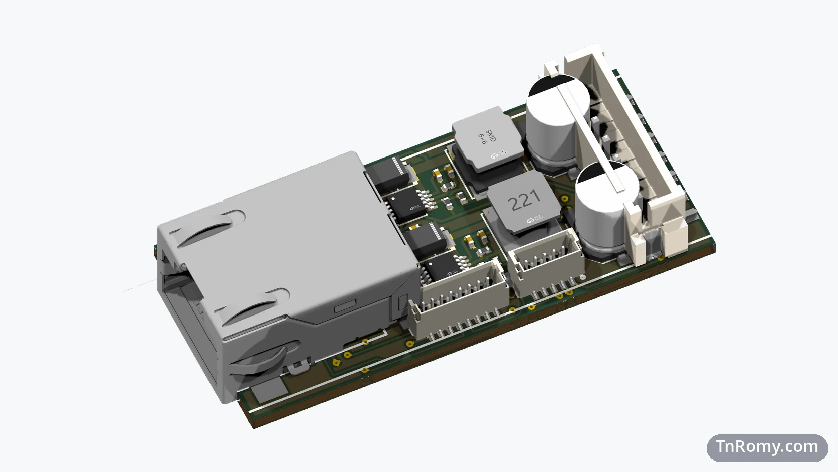
On the first PoE32 Lite board, the fire alarm circuit was not a module. Two H-bridge drivers sat right next to the microcontroller, on the same PCB. It was a first step, but it tied the base board to a single purpose, so for the second revision the circuit had to move out.
v2: a cover that carries a circuit (May 2025)
In v2 the circuit moved onto one of the enclosure's end caps. The aluminium caps were going to be replaced by PCBs anyway, so the rear cap could carry the fire alarm circuit and close the enclosure at the same time. It was connected to the main board through a small 1 mm JST connector.
That connector turned out to be the weak point. The module needs 24 V, and on a 1 mm pitch the 24 V pin kept shorting to its neighbour. The JST connector also needs special pre-made cables, which makes the module harder to build and harder for anyone else to work on.
v3: a standard header and a light (December 2025)
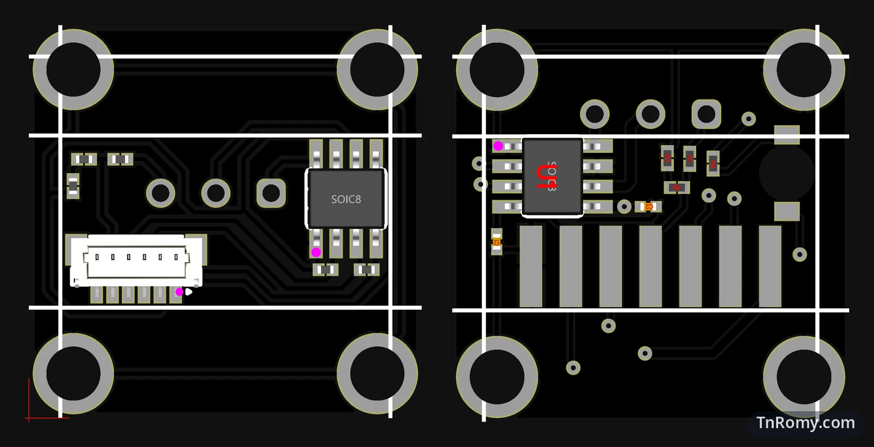
For v3 I redesigned the module around a standard 2.54 mm pin header. The wider pitch gives 24 V a safe distance from the next pin, and a 2.54 mm header is something everyone already has and knows how to use. PoE32 Lite v3 got the matching header on its side, with the same pin order. The same redesign added a status LED that shines through the cover itself.
This is the revision that works. It is stable, and the only thing keeping it out of real installations is the base board: it waits for PoE32 Lite v4.
Design decisions
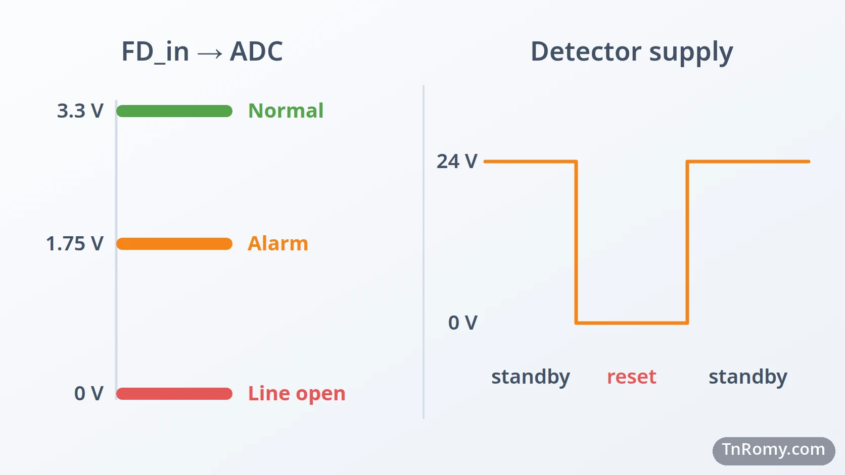
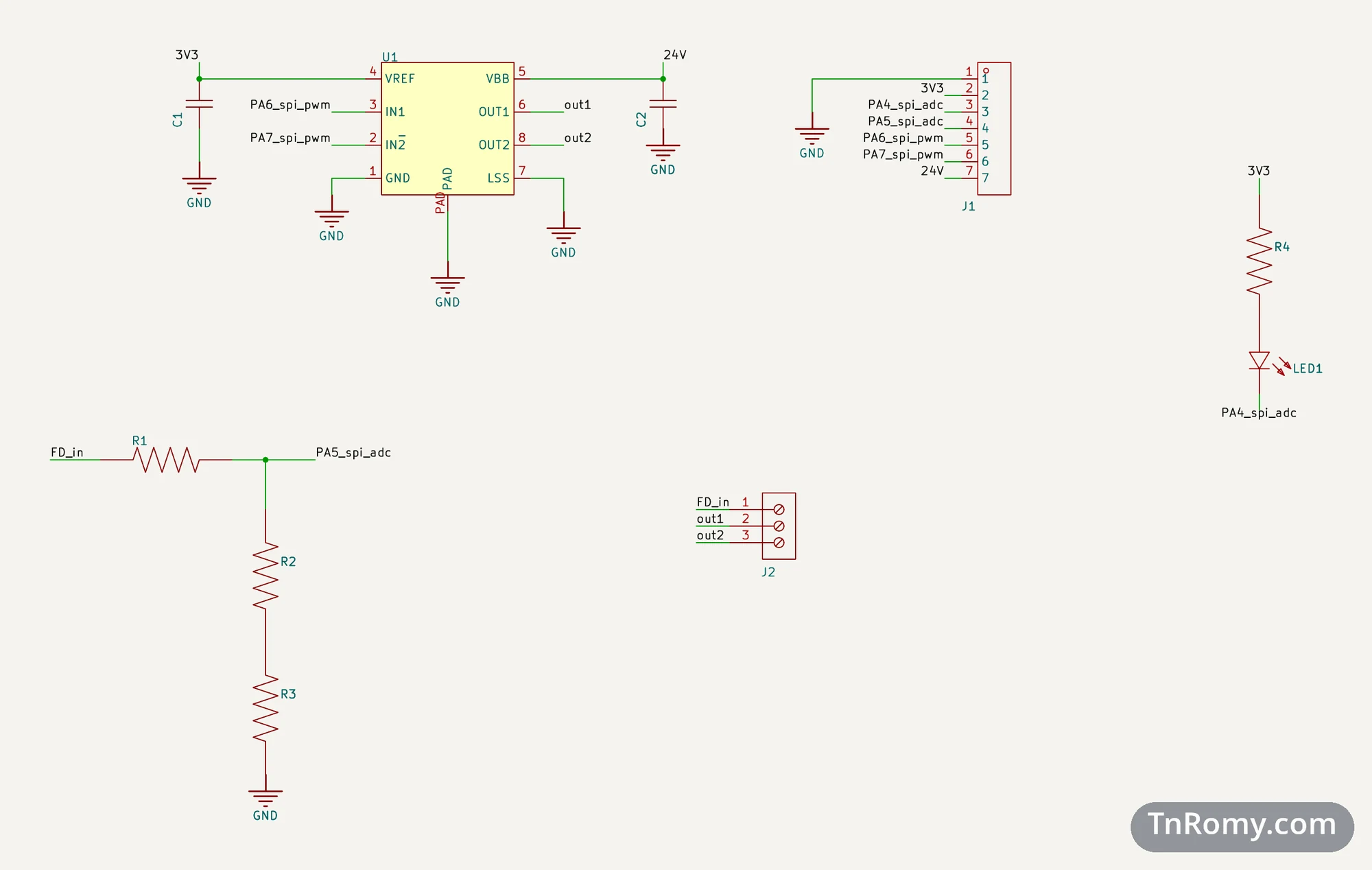
The detector line is switched, not just wired. The detector line is driven by an Allegro A4950, an H-bridge driver that runs from the 24 V rail and is controlled by two PWM pins of the microcontroller. In normal operation it puts 24 V on the line and the detector stands by. To reset a detector after an alarm, the firmware drives both outputs to 0 V for a moment: the detector sees 0 V on its positive terminal and on its ground, switches off, and resets. Then the outputs go back to 24 V and the detector returns to standby.
One analog input reads three states. The detector line comes back through a voltage divider into an ADC pin. When the line is normal, the divider gives the microcontroller about 3.3 V. When a detector goes into alarm, the line voltage drops, and the divider gives about half of that, around 1.75 V. When the line is cut, no current flows through the divider at all, and the lower resistor pulls the input to 0 V. Reading one analog value is enough to tell normal, alarm, and a broken line apart.
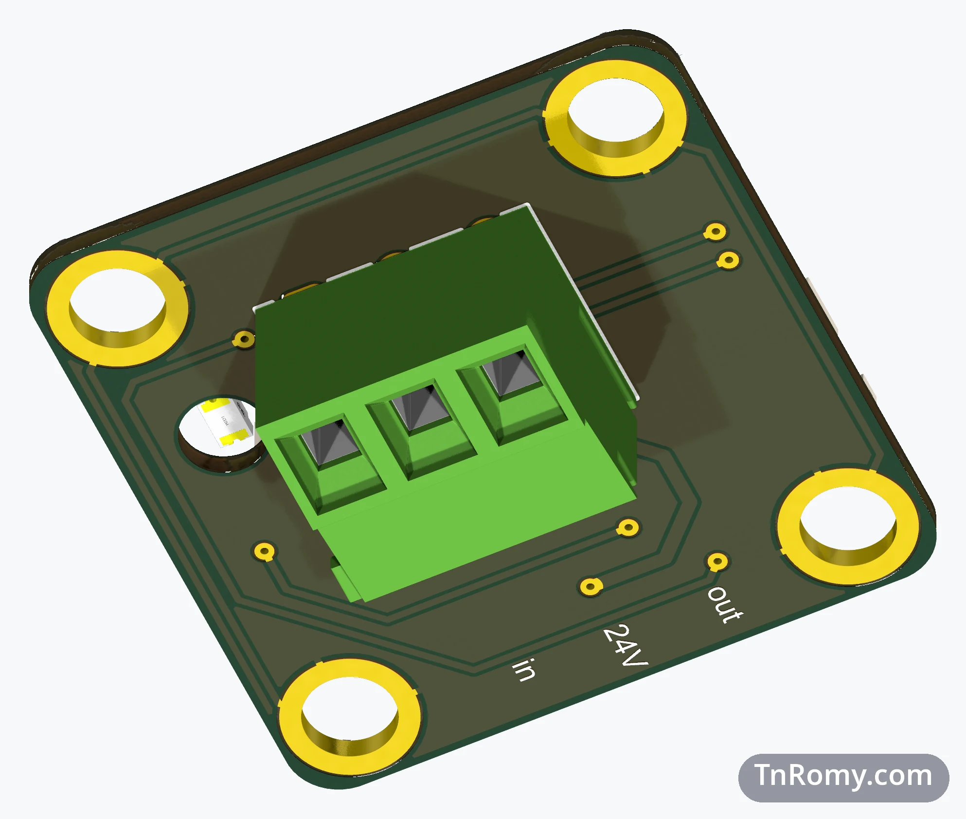
A light without anything sticking out. The LED is a reverse-mount part, soldered on the inside of the cover and shining through a 3.2 mm hole. From the outside the enclosure shows a small light and nothing that can catch or break off.
The field cable stays outside. The terminal block for the detector line is a top-entry type mounted on the outer face of the cover, so the field cable connects on the outside of the enclosure.
The cover is grounded. The four bolt holes are plated and connected to ground, so the cover, and through it the aluminium enclosure, are tied to the circuit's ground.
How it watches a detector
Pinout
| Connector | Pins |
|---|---|
| J1 · header to PoE32 Lite, 2.54 mm, 7 pins | GND · 3.3 V · PA4 (LED) · PA5 (FD_in, ADC) · PA6 (driver IN1, PWM) · PA7 (driver IN2, PWM) · 24 V |
| J2 · terminal block, 3 pins | FD_in · OUT1 · OUT2 |
Mechanics
The module has the same outline as every PoE32 Lite end cap: 24.9 × 24.9 mm with 2 mm corners, 1.0 mm thick, and four plated bolt holes of 3.42 mm, centred 2.825 mm from the edges. The driver, the resistors, the LED, and the header sit on the inside; only the terminal block and the light are visible from the outside.
What it taught me
Pick the connector for the highest voltage it carries. A 1 mm pitch was fine for logic signals and wrong for 24 V. The pin header costs a little more space and gives the 24 V pin the distance it needs from its neighbour.
Standard parts make a module easier to share. A header that anyone can solder and a cable that anyone can make matter more for a module meant to be reused than saving a few millimetres.
The fire alarm is the first rear module, not the last. The same outline and the same header can carry other jobs: a PT100 temperature input, a relay, a MOSFET switch, a DC motor driver, a buzzer or siren driver, or a radio. Each of them only has to fit the cover and use the four microcontroller pins and two rails that PoE32 Lite already provides.
Related
The base board this module closes and plugs into.
Terms
- SDFA
- Software Defined Fire Alarm: a fire alarm in which every detector or siren is a network node and the alarm logic runs in software.
- H-bridge
- A driver of four switches that can drive a load in either direction, or turn it off by putting both sides at the same voltage.
- Voltage divider
- Two or more resistors in series whose junction gives a fixed fraction of the voltage across them.
- ADC
- Analog-to-digital converter: the part of the microcontroller that measures a voltage and turns it into a number.
- Reverse-mount LED
- An LED soldered on one side of a board that shines through a hole to the other side.
- Top-entry terminal block
- A screw terminal whose wires go in from above, perpendicular to the board.
Technologies covered
- Altium Designer
- H-Bridge
- PCB Design
Attachments
-
Download
SDFA-Module-v3.step (zip)
3D model of the SDFA Module v3 with components, STEP format
973.0 KB