PoE32 Lite
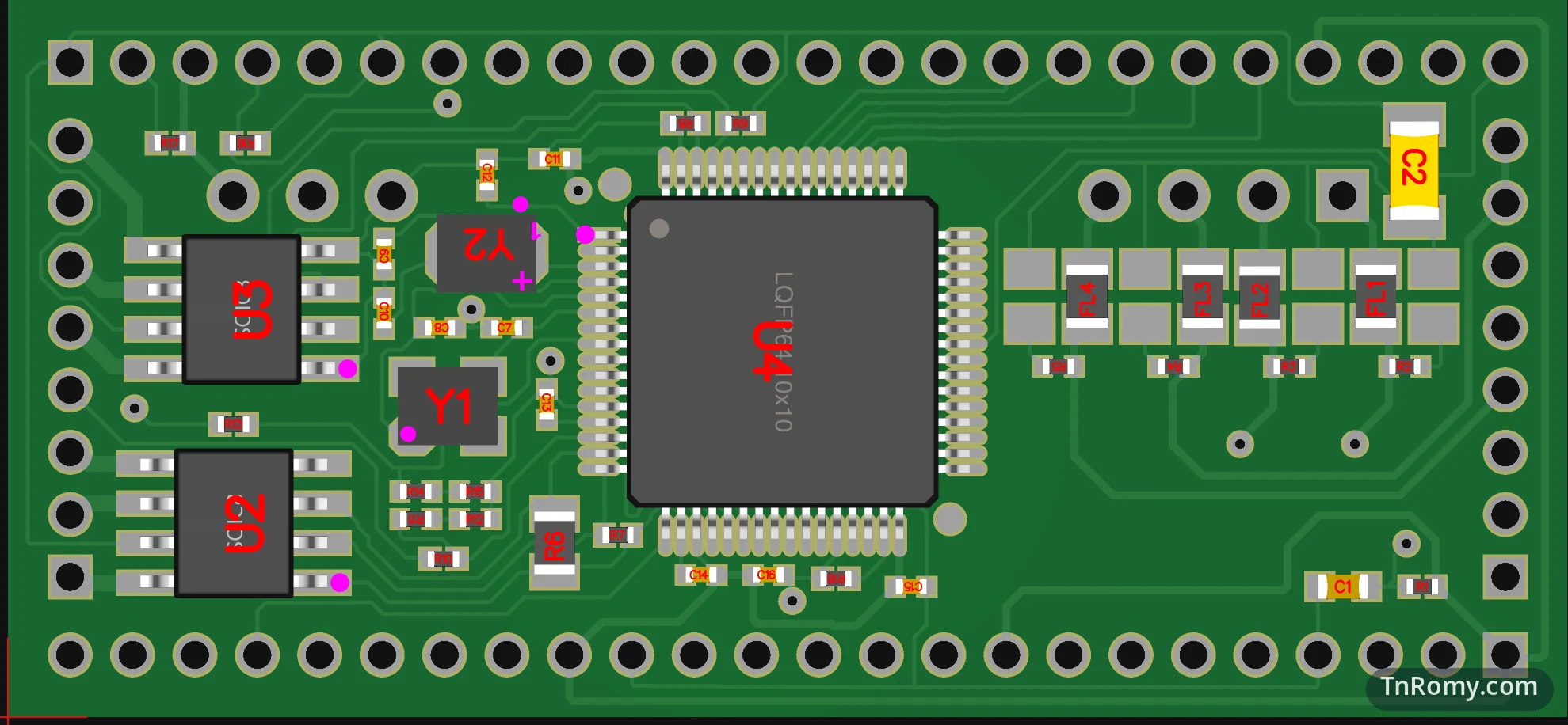
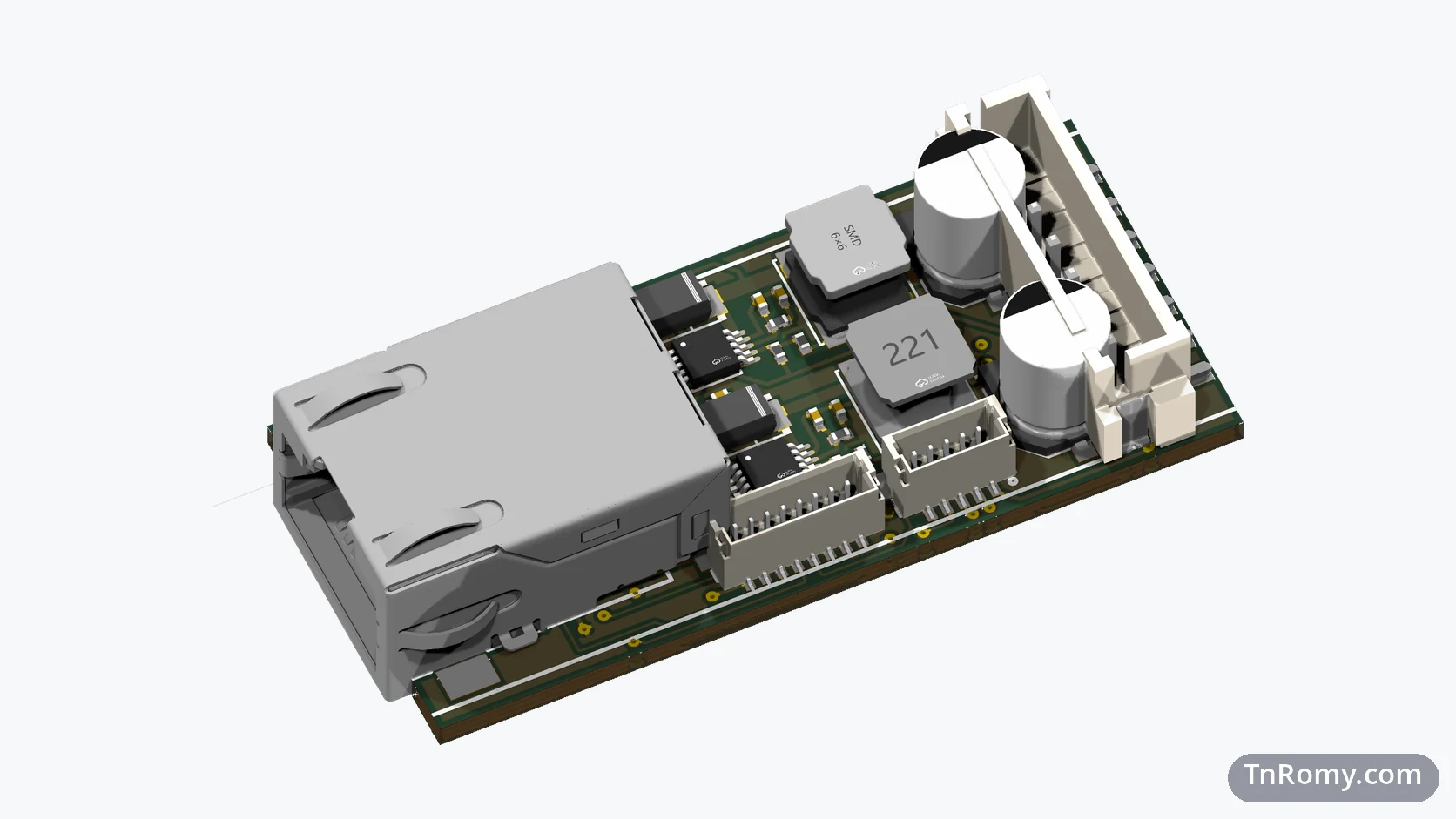
PoE32 Lite is a small microcontroller board that takes both its data and its power from a single Ethernet cable. It is called Lite because its chip, the CH32V203, supports Ethernet at 10 Mbit/s only; a later board built on another chip will do Fast Ethernet, 100 Mbit/s. This page is about its first revision, v1, ordered in April 2025: the board where I put everything together for the first time, and which showed me what the base board should and should not carry.
Later revisions have their own pages. This one stays with v1: what it was, why it looked the way it did, and what it taught me.
At a glance
| Board | PoE32 Lite, the base board of the PoE32 family |
|---|---|
| Revision | v1, ordered on 14 April 2025 |
| MCU | WCH CH32V203RBT6, RISC-V, with the Ethernet MAC and a 10BASE-T PHY on the chip |
| Power | A ready-made Power over Ethernet module, soldered straight onto the board |
| On the board | The microcontroller and two H-bridge drivers for a fire alarm line |
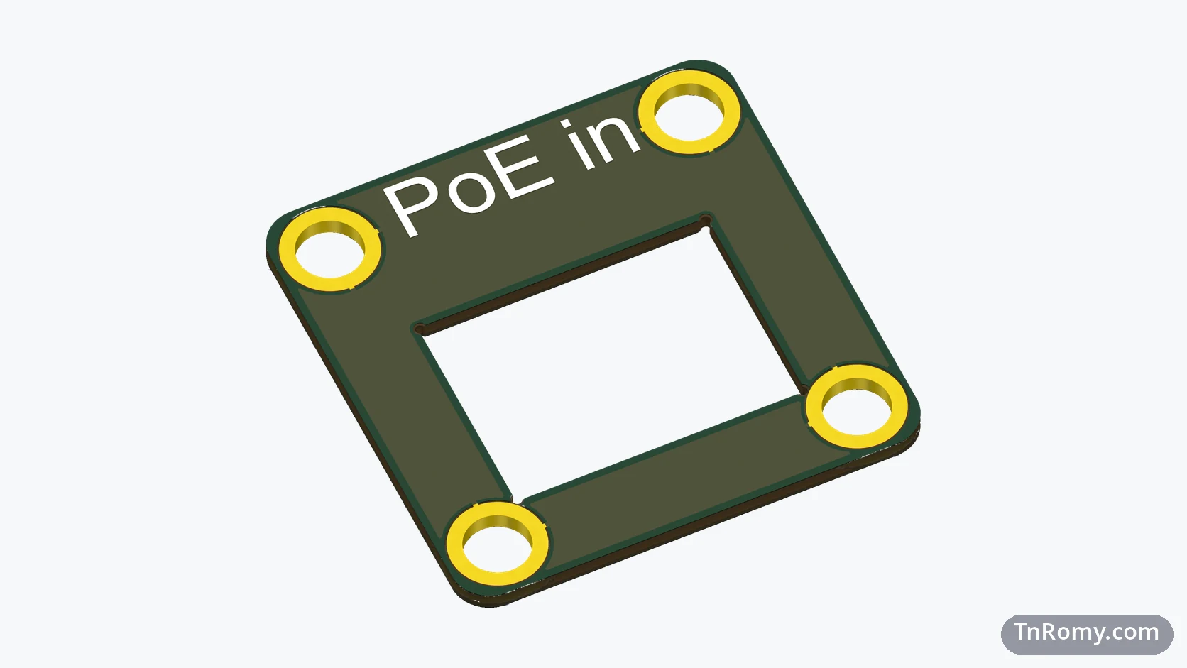
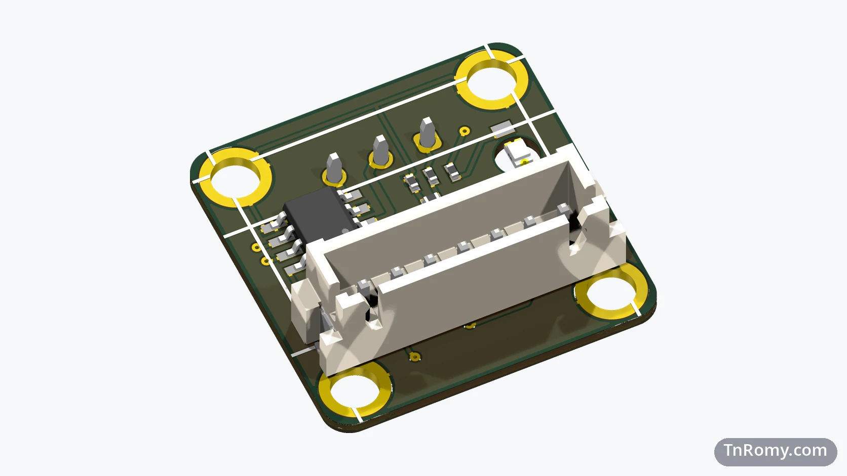
| Ethernet port | Not on the board: the RJ45 sat on a separate small breakout board |
| Status | A first concept; replaced by v2 |
| Files | Component values and the bill of materials are not published |
Why it exists
The board most people reach for in a small connected device today is an ESP32, and it talks over WiFi. But the word wireless in WiFi only describes the data. The power still arrives over a wire, unless the device runs on a battery, and a battery runs out sooner or later. So in practice one cable ends up plugged into the board anyway. If there is going to be one cable regardless, I would rather it be an Ethernet cable: with Power over Ethernet, that single cable carries the data and the power together.
Most of these devices also never move. A sensor on a wall, a controller in a panel, a node of a fire alarm: they stay where they were installed for years. Mobility is the one thing WiFi gives that a cable cannot, and a stationary device does not need it. What a stationary device does need is a link that stays up, and a cable is more stable than radio.
Speed is not a reason to avoid a cable either. Ten megabits per second is plenty for telemetry and MQTT, which is what these devices exchange. And there is security. A WiFi device can be reached by anyone within radio range, so its attack surface extends past the walls of the building. A device on a cable can only be reached by someone who has, at the very least, physical access to the same network.
The size follows from where such a board ends up: tucked behind a ceiling, inside a junction box, next to a detector. So it has to be as small as I can make it, and it has no DC jack at all. Power comes only from the Ethernet port. When a device has to run from a separate supply, a PoE injector does the job, and the power still arrives over the Ethernet cable.
What v1 was
The first board put everything in one place. The CH32V203 sat next to two H-bridge drivers that drive a fire alarm detector line, so the microcontroller and the application shared one board. Power came from a ready-made PoE module, soldered straight onto the board through rows of through-hole pins along both long edges. There was no Ethernet port on the board itself: the RJ45 lived on a separate small breakout board that I ordered together with it.
Design decisions
A microcontroller with Ethernet inside. The CH32V203RBT6 is the cheapest chip I could find with both the Ethernet MAC and the PHY integrated, at around 1.8 USD. The only other candidate I found, the CH32V317WCU6, costs about a dollar more. Because the MAC and a 10 Mbit/s PHY are on the chip, it connects straight to Ethernet magnetics, without an external Ethernet chip such as the W5500, ENC28J60, or LAN8720 adding to the parts, the assembly cost, and the space. Every later revision keeps this chip.
A ready-made PoE module. For a first board I did not design the PoE power stage myself. A finished module, soldered on, gave the board its power and let me concentrate on the microcontroller side.
The application on the same board. The fire alarm drivers sat right next to the microcontroller. For a first concept, one board that does one job was the quickest way to see the whole thing work.
The firmware is the Embassy-Rust firmware I measured in the paper Where the SRAM Goes. It runs on v1 as well, since every revision uses the same chip; only the GPIO configuration differs from board to board.
What it taught me
The application does not belong on the base board. The next device will need a different application circuit. A base board with the fire alarm drivers built in can only ever be a fire alarm board.
The network port does belong on it. A board that depends on a second board for its own Ethernet is not really one board. The RJ45 had to come onto the main board.
Both lessons became v2: the fire alarm circuit moved off the board, and the RJ45 moved on.
Related
The tool I read the board's serial output with while developing it.
Terms
- Power over Ethernet (PoE)
- Delivering power over the same Ethernet cable that carries the data.
- MAC and PHY
- The two halves of an Ethernet interface: the MAC handles frames, and the PHY turns them into signals on the cable.
- H-bridge
- A driver of four switches that can drive a load in either direction, or turn it off.
- Breakout board
- A small board that carries one part, such as a connector, and brings its pins out to wires or headers.
Technologies covered
- Altium Designer
- CH32V203
- Microcontrollers
- PCB Design
- RISC-V
- Ethernet
- Power over Ethernet