PoE32 Lite
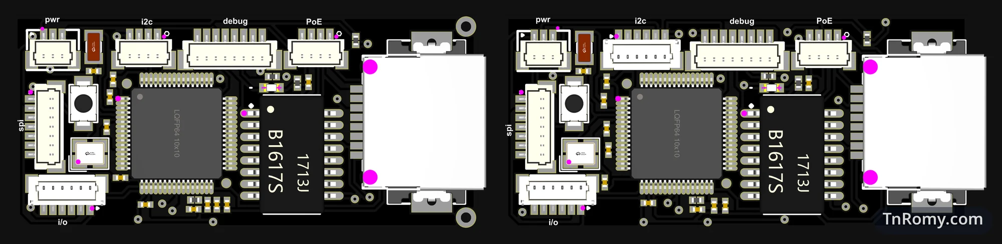
PoE32 Lite is a small microcontroller board that takes both its data and its power from a single Ethernet cable. It is called Lite because its chip, the CH32V203, supports Ethernet at 10 Mbit/s only; a later board built on another chip will do Fast Ethernet, 100 Mbit/s. This page is about its second revision, v2, ordered in May and again in June 2025: the revision that started from the enclosure, brought the Ethernet port onto the board, and moved the fire alarm circuit out to its own module.
The first revision has its own page; here I only say what it lacked. Everything else on this page is about v2.
At a glance
| Board | PoE32 Lite, the base board of the PoE32 family |
|---|---|
| Revision | v2, ordered on 27 May 2025, and corrected as "PoE32 Essential v1.0.1" on 17 June 2025 |
| MCU | WCH CH32V203RBT6, RISC-V, with the Ethernet MAC and a 10BASE-T PHY on the chip |
| Ethernet | A low-profile RJ45 without magnetics, plus a separate Ethernet transformer |
| Power | An off-the-shelf PoE module that I modified, connected through a small JST connector |
| Enclosure | Extruded aluminium profile with PCB end caps, designed before the main board |
| Status | Worked; replaced by v3 |
| Files | Component values and the bill of materials are not published |
Why it exists
The board most people reach for in a small connected device today is an ESP32, and it talks over WiFi. But the word wireless in WiFi only describes the data. The power still arrives over a wire, unless the device runs on a battery. If there is going to be one cable regardless, I would rather it be an Ethernet cable: with Power over Ethernet, that single cable carries the data and the power together.
Most of these devices never move, and a stationary device needs a link that stays up more than it needs mobility; a cable is more stable than radio. Ten megabits per second is plenty for telemetry and MQTT. A device on a cable can only be reached by someone with physical access to the same network, while a WiFi device can be reached from anywhere within radio range. And because such a board ends up behind a ceiling or inside a junction box, it has to be small, with no DC jack: power comes only from the Ethernet port.
What v1 lacked
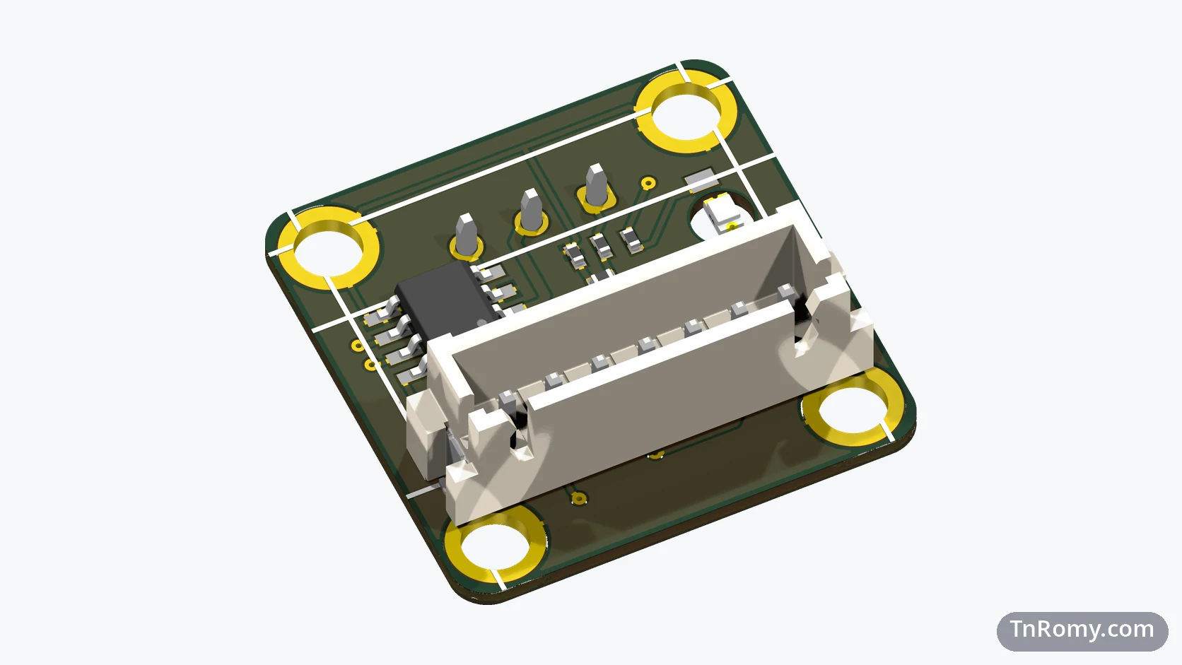
v1 put the fire alarm drivers on the same board as the microcontroller, so the base board could only ever be a fire alarm board. And it had no Ethernet port of its own: the RJ45 sat on a separate breakout board. v2 set out to fix both.
What v2 was
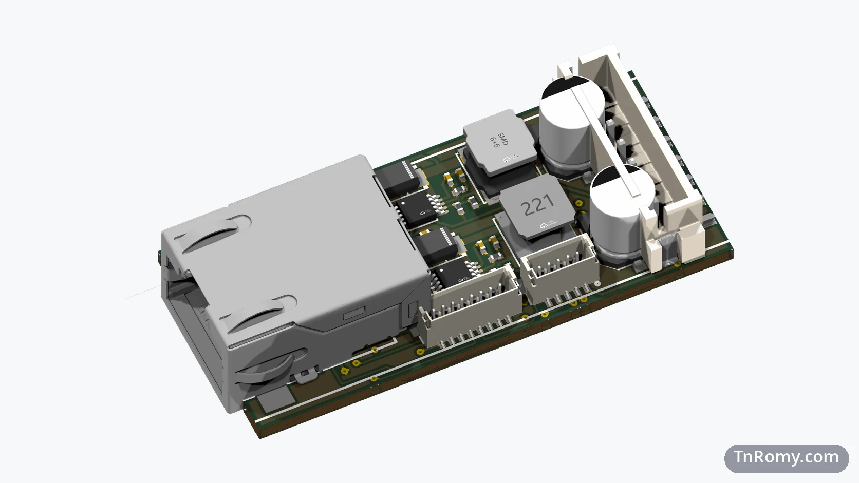
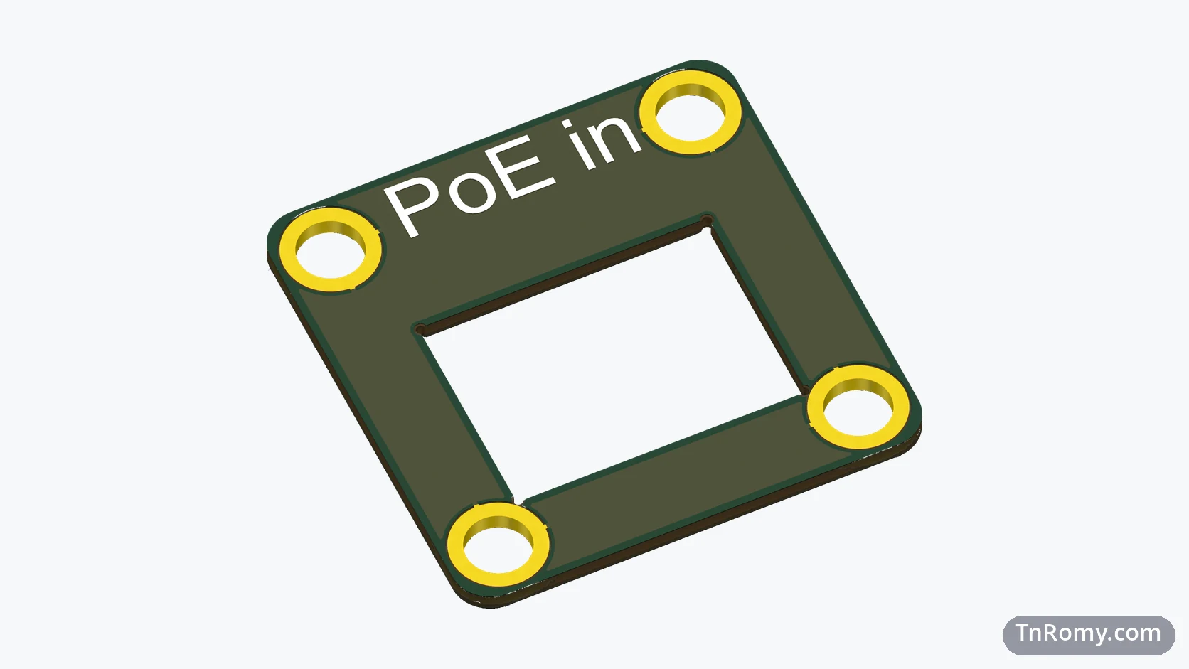
For the second revision I started from the outside. Before drawing any circuit, I designed the two end caps of the aluminium enclosure as PCBs: one with a cut-out for the RJ45, one carrying the fire alarm circuit that used to sit on the v1 board. Only then did the main board get its shape, sized to the rails inside the profile.
I tried to put the PoE power stage on the main board as discrete parts, a PD controller with its own buck converter, and dropped that attempt before routing it. Instead the power came from an off-the-shelf PoE module that I modified, connected through a small JST connector. The main board carried the CH32V203, a low-profile RJ45 without magnetics, and a separate Ethernet transformer.
The low-profile RJ45 was a cosmetic decision as much as a mechanical one. A standard RJ45 stands too tall for the enclosure and sits off-centre against the end cap. A connector that sinks into the board sits right in the middle of the cap's opening. I got the idea from a MikroTik GPeer, an Ethernet extender I took apart: inside was exactly this kind of sunken port, and it looked right to me.
The June order fixed what the May boards revealed: the keep-out area around the RJ45, small relief drills in the inside corners of the connector slot so the router does not leave burrs, room for the board's QR code, and a Bob Smith termination on the Ethernet lines.
The firmware is the Embassy-Rust firmware from the paper Where the SRAM Goes; it runs on v2 with only the GPIO configuration adjusted for this board.
What it taught me
Design the outside first. Drawing the end caps before the main board fixed the space the board had to fit into. Every later revision has been drawn to fit those caps.
The power belongs on the board. v2 worked. But with the power module as a separate part connected by a cable, the arrangement inside the enclosure was far from ideal. The PoE power path had to move onto the main board, and that became v3.
Related
The tool I read the board's serial output with while developing it.
Terms
- Power over Ethernet (PoE)
- Delivering power over the same Ethernet cable that carries the data.
- Powered device (PD)
- The side of a PoE link that receives power, such as this board.
- Magnetics
- The small transformers between an Ethernet chip and the cable; some RJ45 connectors have them built in, the one on v2 does not.
- Bob Smith termination
- Resistors and a capacitor that terminate the unused pairs and the cable-side center taps of an Ethernet port, to reduce electromagnetic interference.
- Relief drill
- A small hole in the inside corner of a cut-out, so the milling tool does not leave a burr there.
Technologies covered
- Altium Designer
- CH32V203
- Microcontrollers
- PCB Design
- RISC-V
- Ethernet
- Power over Ethernet